A gripper that will not open, loses parts, cycles slowly or works only intermittently can be suffering from a pressure drop, incorrect valve connection, leaking fitting, electrical fault or mechanical overload. By following a controlled isolation sequence, you can identify the failed component, verify the HFZ20 application and decide whether to repair one item or replace the complete pneumatic set.
Key takeaways
- Isolate electrical, pneumatic and stored mechanical energy before inspection.
- Test the gripper, valve, air supply and control signal as separate functions.
- Match HFZ20 jaw travel and force to the workpiece, stroke and grip direction.
- Replace the complete set only after confirming the failed component and validating the station.
Make the machine safe and classify the failure before touching a component
Use this sequence for dabaspet pneumatic automation combo gripper for troubleshooting: isolate energy before touching anything.
- Electrical isolate the machine, switch off the isolator, lock it, and verify zero voltage at the valve and control circuit.
- Close the compressed-air shutoff, apply a pneumatic lockout, and bleed downstream pressure until the gauge reads zero. Cycle the control only from a safe position to confirm no trapped air remains.
- Restrain the jaws and support the workpiece or gripper arm. A suspended load can drop, and stored air can close or release the jaws after the signal disappears.
Record every component nameplate, model suffix, thread designation, coil voltage, and sensor type. This combo is not one standardized product; the gripper, valve, FRL, fittings, tubing, flow controls, and sensors have separate limits.
| Symptom | Likely first causes |
|---|---|
| Failure to open | Exhaust blocked, valve signal absent, or seized guide |
| Failure to close | Reversed tubing, failed coil, or blocked supply |
| Weak grip | Low pressure, worn inserts, or excessive gripping moment |
| Uneven jaw movement | Binding, contamination, or unequal flow control |
| Dropped parts | Worn pads, poor grip point, or variable workpiece |
| Slow cycling | Restrictive tubing, clogged silencer, or meter-out set too tight |
| Air leakage | Damaged tube, fitting seal, or gripper seal |
| Intermittent operation | Loose connector, sensor fault, or contaminated spool |
Stop and call a qualified pneumatic technician if isolation cannot be proved, a load remains suspended, wiring is uncertain, or dismantling exposes pressurised components.
Separate the gripper, valve, air preparation and control signal with a live test
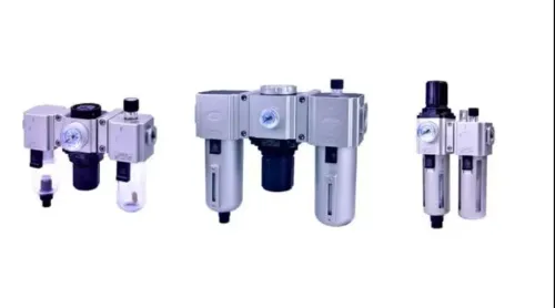
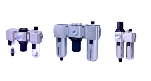
1. Start at the FRL, not the gripper. Inspect the bowl, drain condensate, check the filter element for rust, oil or pipe debris, and confirm the regulator setting at the gripper inlet. For pneumatic gripper problems, Dabaspet maintenance teams should record pressure during opening and closing, not only the static gauge reading.
2. Trace any pressure drop between the regulator and port. Check undersized tube, restrictive push-in fittings, blocked silencers, partially closed flow controls and leaking connections. A normal resting pressure proves little if the gripper starves during the stroke.
3. Run the gripper unloaded. If it cycles freely unloaded but fails with a part, investigate grip load, jaw alignment or mechanical binding. If one direction fails, swap the two actuator hoses at the valve or test each valve outlet independently.
4. Interpret the result by where the fault follows. A fault following the actuator port indicates a cylinder seal, gripper port, tube or mechanical fault; a fault following the valve outlet indicates the valve, coil signal or exhaust path. A blocked exhaust produces slow or incomplete return.
5. Separate remaining symptoms before replacing parts. Damaged seals cause leakage and loss of force; binding causes jerky movement or inconsistent stopping; misadjusted meter-out controls cause one-way slowness; a defective solenoid causes intermittent or absent switching despite an apparently correct command.
Dabaspet pneumatic gripper problems need this repeatable split between air preparation, tubing, actuator and control.
Verify HFZ20 force, jaw travel and mechanical suitability against the real workpiece
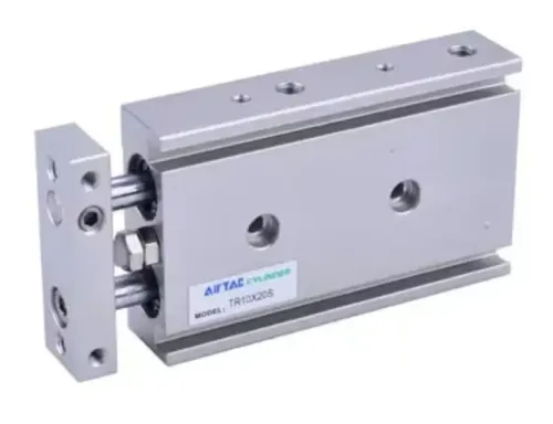
Do not use the HFZ20 catalog maximum as its working grip. Obtain the exact manufacturer datasheet for the purchased model and suffix, then compare its force curve with the real workpiece and operating cycle.
- Record required operating pressure, allowable pressure range, gripping-force values at specified pressures, stroke or jaw travel, port size, jaw orientation and compatible mounting details. Pressure multiplied by effective piston area gives theoretical actuator force, not usable holding force; seal friction, pressure loss, jaw geometry, leverage and motion reduce it.
- Calculate the holding requirement from part mass, coefficient of friction, jaw geometry, acceleration and a safety factor. Check gripping moment and leverage at the actual contact point, including side loading and any external moment.
- Inspect jaw-pad condition, contamination, wear, parallelism, gripping position and workpiece variation. A part near the jaw tip, an oval or variable diameter, or forced misalignment can cause slipping, seal wear and guide wear even when the jaws complete their stroke.
- Reject the combination when servo positioning demands exceed gripper control, severe shock exceeds the rated moment, hygiene documentation is mandatory but unavailable, or the load approaches the gripper limit. Do not exceed rated pressure to compensate for poor geometry.
Check the 4V210-08 DC24V valve against the exact schematic and nameplate
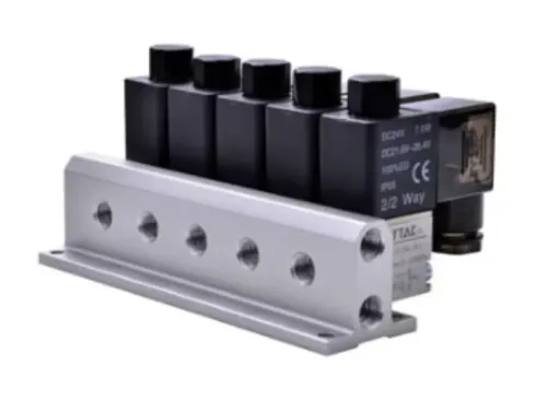
1. Before wiring, photograph the purchased 4V210-08 DC24V nameplate and match its exact model, coil marking and datasheet to the machine order. Do not assume coil wattage, IP rating, connector pinout, polarity or port labels from appearance.
2. Follow the manufacturer’s schematic to identify the supply port, exhaust ports and both actuator lines. Inspect exhaust routing and mufflers for kinks, contamination or blockage, then record the verified port map on the machine drawing. Reversed actuator lines swap jaw direction; blocked exhaust traps back-pressure and can prevent movement or slow the return stroke.
3. Command each PLC output and confirm its diagnostic status. Measure voltage directly across the coil terminals while the output is energised, check coil continuity with power isolated, verify connector pinout and polarity, and operate the valve’s manual override. A lit connector LED does not prove adequate loaded coil voltage or a free spool.
4. If the valve passes these checks, swap the two actuator hoses or test each outlet independently. If the fault follows the outlet, investigate the valve, coil signal or exhaust; if it follows the hose or actuator port, investigate tubing, seals, binding or the gripper.
5. Record pressure, regulator setting, loaded coil voltage, tube size, fitting type and confirmed jaw direction in the commissioning record.
Correct fitting, tubing and air-circuit errors that create recurring pneumatic component set issues
Select pneumatic fittings for gripper systems dabaspet by tube outside diameter, port thread, sealing method, pressure and temperature ratings, bend radius, flow capacity and exhaust-control needs—not appearance. Match G or BSPP, R or BSPT, or NPT exactly; thread diameter alone is insufficient.
Use the specified seal, keep tape and sealant away from the first threads, and prevent debris entering the valve.
- Cut tube square, deburr it, insert it to the fitting’s full marked depth, and avoid side loading or a tight bend at the collet. Cross-threading, an undersized tube, or an elbow in a small-bore circuit can cause recurring pneumatic component set issues dabaspet; choose a straight fitting where flow and response matter.
- Drain the FRL bowl, inspect for leaks, verify tube cuts, and retighten only within the fitting maker’s stated limit. Check jaw-pad wear, mounting-bolt security and rising cycle time.
Record these details before replacement:
| Station | Symptom | Evidence to record |
|---|---|---|
| Dabaspet cell | Leak or slow cycle | FRL and gripper pressure, valve part number, coil voltage, tube dimensions, leak location, workpiece mass, jaw position and connection photographs |
Choose repair or complete-set replacement, then validate the corrected station
Repair one component when failure isolation is clear, a tested spare is available, and the shared circuit is clean; replace the complete combo when wear, contamination or unknown compatibility affects several parts.
Stop using the application when the part can escape into a hazard zone, fail-safe action is unproven, or no correctly rated replacement is available.
| Option | Downtime and evidence | Air-circuit concern |
|---|---|---|
| Repair one component | Shortest downtime after confirmed diagnosis; retain sound parts | Leak-test shared tubing, valve and fittings for contamination |
| Replace complete combo | Faster than repeated fault-finding when spares are unavailable or wear is widespread | Clean FRL, tubing and exhaust paths before installation |
| Stop application | Required after uncontrolled motion, dropped parts or failed air-loss response | Isolate pressure until the root cause is corrected |
Before restart, match every model suffix and confirm Dabaspet availability of fittings, tubing, brackets, flow controls and connectors. Check reed or solid-state sensor supply, polarity, connector pinout, switching position and PLC input type; an LED alone proves nothing. Leak-test every connection, run several unloaded cycles, then loaded cycles with the actual workpiece.
Remove air and verify the gripper holds or releases safely, and prove a dropped part cannot enter the hazard zone. For exact Airtac replacements and pneumatic fittings for gripper systems Dabaspet, Hakimi Pneumatic & Hardware can help match components; maintenance must verify datasheets and installation requirements before commissioning.
Related product
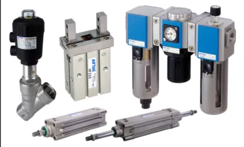
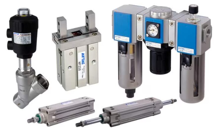
 | Pneumatic Component Set Pneumatic Automation Combo – Gripper, Cylinders, FRL, Angle Seat Valve This curated pneumatic combo set brings together essential components for industrial automation. View product → |
Frequently asked questions
What should you do before troubleshooting a Dabaspet pneumatic automation combo gripper?
Stop the machine, isolate electrical and compressed-air energy, exhaust trapped pressure, secure moving parts and confirm zero energy before touching components.
How can you separate gripper, valve, air-preparation and control faults?
Run a controlled live test using the schematic: check supply pressure, send the 4V210-08 DC24V signal, observe valve actuation and test gripper movement independently.
How do you verify that an HFZ20 gripper suits the workpiece?
Compare required gripping force, jaw travel, finger length, grip direction, load centre and workpiece shape with the HFZ20 specifications and the actual application.
What causes recurring pneumatic fittings and component-set problems?
Look for incorrect tube size, loose or damaged fittings, cut tubing ends, leaks, contaminated air, incorrect flow-control orientation and unsupported tubing.
When should you replace the complete pneumatic component set?
Replace the set when multiple matched components are damaged, compatibility is uncertain or repair cannot restore repeatable gripping; validate pressure, stroke, timing and part retention afterward.
Keywords